13. Action Package
The Action package defines a set of meta-model elements whose purpose is to represent implementation-level behavior descriptions determined by programming languages, for example statements, operators, conditions, features, as well as their associations, for example control and data flow. Action package extends the KDM Code package. As a general rule, in a given KDM instance, each instance of an action element represents some programming language construct, determined by the programming language of the existing software system. Each instance of an action meta-model element corresponds to a certain region of the source code in one of the artifacts of the software system. An action element usually represents one or more statements, and an action relationship usually represents a usage of a name in a statement.
Organization of the Action Package
The Action package consists of the following 11 class diagrams:
- ActionElements
- ActionFlow
- ActionInheritances
- CallableRelations
- DataRelations
- ExceptionBlocks
- ExceptionFlow
- ExceptionRelations
- InterfaceRelations
- UsesRelations
- ExtendedActionElements
The Action package depends on the following packages:
ActionElements Class Diagram
In general, the Action package follows the uniform pattern for KDM models and extends the KDM Framework with specific meta-model elements related to implementation-level behavior. The Action package deviates from a uniform pattern for KDM models because the Action package does not define a separate KDM model, but rather extends the Code model, defined in the Code package. Therefore each Action element is a subclass of AbstractCodeElement. Action package defines most of the relationship types to the Code model. Together, Action and Code packages constitute the Program Elements Layer of KDM.
The ActionElements diagram defines the following classes determined by the KDM model pattern:
- ActionElement – main class of the Action package.
- AbstractActionRelationship – a class representing an abstract parent of all KDM relationships that can be used to represent actions (in general, related to usages of names in programming language statements)
The class diagram shown in See – ActionElements Class Diagram. captures these classes and their relations.
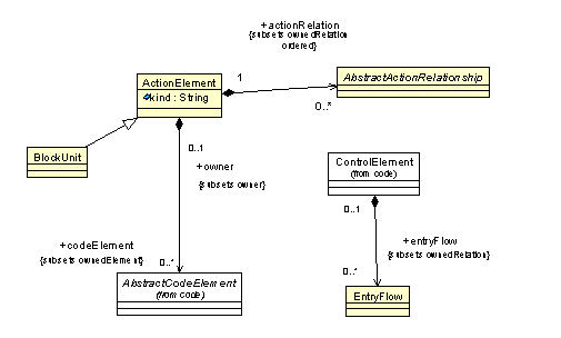
– ActionElements Class Diagram
ActionElement Class
The ActionElement is class to describe a basic unit of behavior. ActionElements are endpoints for primitive relations. ActionElement can be linked to the original representation through the SourceRef element from the Source package.
| kind:String | represents the meaning of the operations, performed by the ActionElement. |
ActionElement may own StorableUnit or ValueElement and their subclasses and nested action elements
An action element represents a unit of behavior. It can represent one or more programming language statements, or even a part of a programming language statement. It is the implementer’s responsibility to select the granularity of the action elements. As a minimum, each ControlElement should own at least one ActionElment so that it can be the endpoint of all ActionRelationships originating from the corresponding ControlElement. Static analysis grade KDM implementations should use well-defined fine grained ActionElements, specified as the “micro KDM” compliance point.
Data elements owned by the ActionElement represent temporary variables or values used by the action element. Action elements may be nested, when one ActionElement instance is a container for other ActionElements.
For micro KDM compliance the list of the allowed action element kind values and their meaning is described in Appendix 1. For non-micro KDM implementation, the value of the kind is not normative.
It is the implementer’s responsibility to map programming language statements and other descriptions of behavior into KDM ActionElements.
An ActionElement can own other ActionElements. Such ActionElement is called a “composite action”. Composite action represents an entire set of leaf actions owned directly or indirectly.
AbstractActionRelationship Class (abstract)
The AbstractActionRelationship is the parent class representing various KDM relationships which originate from an ActionElement.
Usually, an action relationship corresponds to some usage of a name in a programming language statement. Action relationships originate from ActionElements as opposed to code relationships which originate from code elements. AbstractActionRelationship is subclassed by several concrete action relationship meta-elements.
BlockUnit Class
The BlockUnit represents logically and physically related blocks of ActionElement, for example, blocks of statements.
| codeElement:AbstractCodeElement[0..*] | owned code elements, including nested BlockUnits |
A BlockUnit is a logical container for action elements. BlockUnit is similar to a composite ActionElement which can also contain nested ActionElement and data elements. BlockUnit represents the entire set of leaf Actions, owned by the BlockUnit directly or indirectly.
ControlElement (additional properties)
| entryFlow:EntryFlow[0..*] | EntryFlow relationships that associate the given control element and some action elements owned by it, which are designated as the entry actions. |
Control flow is transferred to the Entry actions when the ControlElement that owns them is called. Multiple EntryFlow elements represent nondeterministic control flow.
ActionInheritances Class Diagram
The ActionInheritances class diagram is determined by the uniform pattern for extending the KDM framework. Action package does not define a separate KDM model, but extends the Code model. The class diagram shown in See – ActionInheritances Class Diagram. captures these classes and their associations.

– ActionInheritances Class Diagram
ActionFlow Class Diagram
The ActionFlow class diagram provides basic meta-model constructs to define the control-flow between ActionElements. The class diagram shown in See – ActionFlow Class Diagram. captures these classes and their relations.
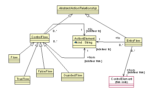
– ActionFlow Class Diagram
ControlFlow Class (generic)
The ControlFlow is a generic modeling element that represents control flow relation between two ActionElements. It is further subclassed with more specific modeling elements. ControlFlow class could be used to represent programming constructs that are not covered any of the specific subclasses as an extension point.
| from:ActionElement[1] | the origin of the control flow |
| to:ActionElement[1] | the target of control flow, when represent the next action element in the trace determined by the control flow |
ControlFlow class should always be used with a stereotype.
From the KDM representation perspective, ControlFlow meta-element is an extension point which can be used as the base element for new “virtual” meta-model elements, representing specific control flow relationships not covered by the semantic categories of its concrete subclasses. From the meta-model perspective, the ControlFlow element defines the common properties of various control flow relationship representations in KDM.
Multiple ControlFlow elements represent nondeterministic choice of behavior.
It is the implementer’s responsibility to map control flow mechanisms of the given programming language into ControlFlow meta-elements. It is implementer’s responsibility to adequately represent the control flows of the existing system by a a set of action elements and ControlFlow relationships between them.
EntryFlow Class
The EntryFlow is a modeling element that represents an initial flow of control inside a ControlElement into the first ActionElement of the ControlElement.
- Each ControlElement or its subclass such that it owns one or more ActionElement should have a corresponding EntryFlow relationship in which the “from” attribute is the ControlElement
- The “to” attribute of an EntryFlow element should be an ActionElement that is owned by the ControlElement that is the “from” attribute of the EntryFlow
The “entry” action element is the first action element in a trace which corresponds to the behavior of the owner ControlElement. Multiple action element which are the designated as “entry” actions, represent a nondeterministic choice, i.e. several possible trace families, each of which start with a different “entry” action element.
Flow Class
The Flow class is a modeling element that represents control flow relationship between two ActionElements such that the the ActionElement that corresponds to the “to” attribute of the Flow is a successor of the ActionElement that corresponds to the “from” attribute of the Flow.
If there is one or more Flow elements there should be no TrueFlow, FalseFlow or GuardedFlow with the same action element as the “from” attribute.
If there exists two or more Flow element, such that they share the same ActionElement as the “from” attribute, they represent an unspecified flow of control.
TrueFlow Class
The TrueFlow class is a modeling element that represents control flow relationship between two ActionElements such that 1) the ActionElement that corresponds to the “from” attribute of the TrueFlow represents the logical condition; and 2) the ActionElement that corresponds to the “to” attribute of the TrueFlow is a successor of the ActionElement that corresponds to the “from” attribute of the TrueFlow when the value of the condition is true.
If there exists an ActionElement with a TrueFlow element, there should be no GuardedFlow or Flow elements have the same ActionElement as the “from” attribute; (but there can be FalseFlow).
If there exists two or more TrueFlow element, such that they share the same ActionElement as the “from” attribute, they represent an unspecified flow of control. If there is no FalseFlow element, then the current ActionElement is terminal, when condition is not satisfied
FalseFlow Class
The FalseFlow class is a modeling element that represents control flow relationship between two ActionElements such that 1) the ActionElement that corresponds to the “from” attribute of the FalseFlow represents the logical condition; and 2) the ActionElement that corresponds to the “to” attribute of the FalseFlow is a successor of the ActionElement that corresponds to the “from” attribute of the FalseFlow when the value of other conditions are not satisfied. FalseFlow represents the “default” control flow branch in representing conditional statements and switch statements. FalseFlow is a specific modeling element that is used in combination with either TrueFlow or GuardedFlow.
If there exists a FalseFlow element, there should be either 1) a corresponding TrueFlow element such that the both the TrueFlow and the FalseFlow elements has the same ActionElement as the “from” attribute; or 2) one or more GuardedFlow elements that have the same ActionElement as the “from” attribute; and 3) there are no other relationship elements that are subclasses of FlowRelationship that have the same ActionElement as the “from” attribute;
If there exists two or more FalseFlow element, such that they share the same ActionElement as the “from” attribute, they represent an unspecified flow of control.
GuardedFlow Class
The GuardedFlow class is a modeling element that represents control flow relationship between two or more ActionElements such that 1) the ActionElement that corresponds to the “from” attribute of the GuardedFlow represents the selection statement (for example, a “switch” statement); and 2) the ActionElement that corresponds to the “to” attribute of the GuardedFlow represents the guarding condition which determines a branch of control flow; and 3) the branch of control flow determined by the ActionElement that corresponds to the “to” attribute of the GuardedFlow element is a successor of the ActionElement that corresponds to the “from” attribute of the GuardedFlow when the guarded condition in the context of the selection statement is satisfied. FalseFlow element can be used in combination with one or more GuardedFlow elements to represent the default branch of control flow, for example, to represent the default branch of a switch statement.
If there exists a GuardedFlow element, there should be no other relationship elements that are subclasses of FlowRelationship that have the same ActionElement as the “from” attribute, with exception of one or more GuardedFlow elements or zero or one FalseFlow element.
CallableRelations Class Diagram
The CallableRelations class diagram defines a set of meta-model elements to represent call-type behavior that associate ActionElement to ControlElement and represent control flows of the existing software system.
The CallableRelations diagram describes the following types:
- Calls – is a modeling element that represents a call-type relationship between an ActionElement and a CallableElement or one of its subclass elements, in which the ActionElement represents some form of a call statement, and the CallableElement represents the element being called.
- Dispatches – is a modeling element that represents an call-type of relationship between an ActionElement and a data item, in which the ActionElement represents some form of a call, and the data item represents a pointer to a procedure type.
The class diagram shown in See – CallableRelations Class Diagram. captures these classes and their relations.
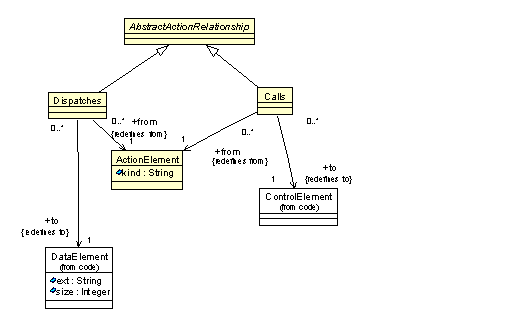
– CallableRelations Class Diagram
Calls Class
Calls is a modeling element that represents a call-type relationship between an ActionElement and a ControlElement or one of its subclass elements. The ActionElement represents some form of a call statement, and the ControlElement represents the element being called. In the meta-model the Calls element is a subclass of ActionRelationship.
| from:ActionElement[1] | the action element from which the call relation originates |
| to:ControlElement[1] | the target ControlElement |
Calls relationship corresponds to the ISO/IEC 11404 “invoke” operation on a procedure type. It can represent a call to a procedure, a static method, a non-static method of a particular object instance, a virtual method or an interface element.
Calls relation to a non-static method should be accompanied by an Addresses relationship to the corresponding object.
Precise semantics of a call can be represented by the “kind” element of the owner ActionElement, according to the guidelines provided in the “micro KDM” compliance point.
Dispatches Class
Dispatches is a modeling element that represents a call-type of relationship between an ActionElement and a data item. The ActionElement represents some form of a call behavior, and the data item represents a pointer to a procedure type.
| from:ActionElement[1] | the action element from which the call relation originates |
| to:DataElement[1] | the data element that represents the pointer to a procedure type |
Dispatches relation does not identify the actual target of the call. Additional analysis of the KDM instance may be required to determine the real targets of the Dispatches call.
<?xml version="1.0" encoding="UTF-8"?>
<kdm:Segment xmi:version="2.1"
xmlns:xmi="http://www.omg.org/XMI"
xmlns:action="http://kdm.omg.org/action"
xmlns:code="http://kdm.omg.org/code"
xmlns:kdm="http://kdm.omg.org/kdm" name="Dispatch Example">
<model xmi:id="id.0" xmi:type="code:CodeModel">
<codeElement xmi:id="id.1" xmi:type="code:CompilationUnit" name="Dispatch.c">
<codeElement xmi:id="id.2" xmi:type="code:CallableUnit"
name="foo" type="id.15" kind="regular">
<codeRelation xmi:id="id.3" xmi:type="code:HasType" to="id.14" from="id.2"/>
<codeElement xmi:id="id.4" xmi:type="code:Signature" name="foo">
<parameterUnit xmi:id="id.5" name="a" type="id.13"/>
<parameterUnit xmi:id="id.6" type="id.13" kind="return"/>
<codeElement xmi:id="id.7" xmi:type="code:CallableUnit"
name="bar" type="id.15" kind="regular">
<codeRelation xmi:id="id.8" xmi:type="code:HasType" to="id.14" from="id.7"/>
<codeElement xmi:id="id.9" xmi:type="code:Signature" name="bar">
<parameterUnit xmi:id="id.10" name="a" type="id.13"/>
<parameterUnit xmi:id="id.11" type="id.13" kind="return"/>
<codeElement xmi:id="id.12" xmi:type="code:StorableUnit" name="pf" type="id.14"/>
<codeElement xmi:id="id.13" xmi:type="code:IntegerType" name="int"/>
<codeElement xmi:id="id.14" xmi:type="code:TypeUnit" name="fp" type="id.15">
<codeElement xmi:id="id.15" xmi:type="code:Signature" name="f">
<parameterUnit xmi:id="id.16" name="a" type="id.13"/>
<parameterUnit xmi:id="id.17" type="id.13" kind="return"/>
<codeElement xmi:id="id.18" xmi:type="code:CallableUnit" name="foobar" type="id.33">
<entryFlow xmi:id="id.19" to="id.20" from="id.18"/>
<codeElement xmi:id="id.20" xmi:type="action:ActionElement" name="a1" kind="Assign">
<actionRelation xmi:id="id.21" xmi:type="action:Addresses" to="id.2" from="id.20"/>
<actionRelation xmi:id="id.22" xmi:type="action:Writes" to="id.12" from="id.20"/>
<actionRelation xmi:id="id.23" xmi:type="action:Flow" to="id.24" from="id.20"/>
<codeElement xmi:id="id.24" xmi:type="action:ActionElement" name="a2" kind="Assign">
<actionRelation xmi:id="id.25" xmi:type="action:Addresses" to="id.2" from="id.24"/>
<actionRelation xmi:id="id.26" xmi:type="action:Writes" to="id.12" from="id.24"/>
<actionRelation xmi:id="id.27" xmi:type="action:Flow" to="id.28" from="id.24"/>
<codeElement xmi:id="id.28" xmi:type="action:ActionElement" name="a3" kind="PtrCall">
<codeElement xmi:id="id.29" xmi:type="code:Value" name="1" type="id.13"/>
<actionRelation xmi:id="id.30" xmi:type="action:Reads" to="id.12" from="id.28"/>
<actionRelation xmi:id="id.31" xmi:type="action:Reads" to="id.29" from="id.28"/>
<actionRelation xmi:id="id.32" xmi:type="action:Dispatches"
<codeElement xmi:id="id.33" xmi:type="code:Signature" name="foobar"/>
DataRelations Class Diagram
The DataRelations class diagram defines a set of meta-model elements which represent data flow relationships between action elements and data elements. The “from” endpoint of these relationship is some ActionElement that represents a statement that involves a data operation. The “to” endpoint represents some code item. Data relationships are shown at See – DataRelations Class Diagram..
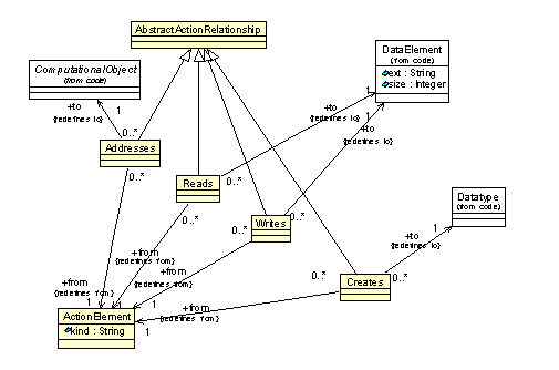
– DataRelations Class Diagram
Reads Class
The Reads relationship represents a flow of data from a DataElement to an ActionElement (read access to the DataElement).
| from:ActionElement[1] | the action element which owns the Reads relationship |
| to:DataElement[1] | the DataElement which is the source of the flow of data |
Reads relationship represents an association between an action element which implements a flow of data from a certain data element to the corresponding data element according to the semantics of the programming language of the existing software system.
Writes Class
The Writes represents flow of data from an ActionElement to a DataElement (write access to the DataElement).
| from:ActionElement[1] | the action element which owns the Writes relationship |
| to:DataElement[1] | the DataElement which is the sink of the flow of data |
Writes relationship represents an association between an action element which implements a flow of data to a certain data element to the corresponding data element according to the semantics of the programming language of the existing software system.
Addresses Class
Addresses relationship represents access to a complex data structure, where the Reads or Writes relationships are applied to the elements of the data structure, or where an address of a data element is taken.
| from:ActionElement[1] | the action element which owns the Addresses relationship |
| to:ComputationalObject[1] | the Computational object which is being accessed |
Addresses relationship represents an association between an action element which receives a reference to a certain data element to the corresponding data element according to the semantics of the programming language of the existing software system.
Creates Class
The Creates represents an association between an ActionElement and a Datatype such that the ActionElement creates an new instance of the Datatype.
| from:ActionElement[1] | the action element which owns the Creates relationship |
| to:Datatype[1] | the DataElement which is the instantiated by the ActionElement |
Creates relationship represents an association between an action element which creates a new instance of a certain data element to the corresponding datatype according to the semantics of the programming language of the existing software system.
ExceptionBlocks Class Diagram
The Exceptions class diagram defines meta-model elements that represent containers involved in exception-handling mechanism common to several programming languages. These classes are illustrated at See – ExceptionBlocks Class Diagram..
Basic try-, catch- and finally-blocks are represented by dedicated containers defined as subclasses of the ExceptionUnit to represent the contents of those blocks. The TryUnit provides the containment to track the dependent Catch clauses and the optional finally block (for languages that support it).
The Catch container can own ParameterUnit to represent the data passed to it by the exception-handling mechanism when this block is activated, the so-called “its catch object”. This allows exceptions to be modeled like any other object and to have their own inheritance. The ParameterUnit that represents the “catch object” of a catch-block has special ParameterKind value kind=”exception” to represent parameter passing via exception mechanism or kind=”catchall” to represent the catch all construct in C++.
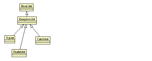
– ExceptionBlocks Class Diagram
ExceptionUnit Class
ExceptionUnit class is a generic meta-model element that provides a common superclass to various KDM containers for representing exception handling. ExceptionUnit is a subclass of a BlockUnit. ExceptionUnit is a KDM container, which can own both ActionElement (for example, statements in the catch-block) as well as CodeItem (for example, parameters to the catch-block, local definitions and nested blocks). ExceptionUnit is a generic element, and KDM models are expected to use concrete subclasses of ExceptionUnit with more precise semantics. However, ExceptionUnit can be used as an extended modeling element with a stereotype. ExceptionUnit is more specific than an BlockUnit.
ExceptionUnit should have a stereotype
TryUnit class
TryUnit class is a meta-model element that represents try-blocks common to several programming languages. TryUnit is a container for action elements and associated definitions of CodeItems. The purpose of a TryUnit is to represent try-blocks and to manage exception flow to related catch-blocks and finally-block (for programming languages that support this concept). In particular, the TryUnit is the origin of ExceptionFlow relations to the corresponding CatchUnits and FinallyUnit blocks, which represent related catch- and finally-blocks. TryUnit may own nested TryUnit blocks.
TryUnit represents a try-block.
CatchUnit class
CatchUnit is a meta-model element that represents catch-blocks. Particular CatchUnit should be associated to a particular TryUnit through ExceptionFlow relation. CatchUnit may contains ParameterUnit that represents the exception object passed to the catch-block by the exception-handling mechanism.
CatchUnit should be associated to a TryUnit. In particular, a CatchUnit should be the target of an ExceptionFlow relationship which originates from some TryUnit.
CatchUnit represents one of the catch-blocks associated with a certain try-block. Usually, one or more CatchUnits follow a TryUnit. Each CatchUnit should be associated with the corresponding TryUnit through an instance of ExceptionFlow relationship.
FinallyUnit class
FinallyUnit is a meta-model element which represents finally-block associated with a certain try-block. The FinallyUnit is associated with the core responding TryUnit through an ExitFlow relation.
FinallyBlock should be associated to a TryUnit. In particular, a FinallyUnit should be the target of an ExitFlow relationship which originates from some TryUnit.
FinallyBlock represents a finally-block associated with a certain try-block.
.<?xml version="1.0" encoding="UTF-8"?>
<kdm:Segment xmi:version="2.1"
xmlns:xmi="http://www.omg.org/XMI"
xmlns:action="http://kdm.omg.org/action"
xmlns:code="http://kdm.omg.org/code"
xmlns:kdm="http://kdm.omg.org/kdm" name="Exceptions Example">
<model xmi:id="id.0" xmi:type="code:CodeModel">
<codeElement xmi:id="id.1" xmi:type="code:ClassUnit" name="A">
<codeElement xmi:id="id.2" xmi:type="code:MethodUnit" name="foo">
<entryFlow xmi:id="id.3" to="id.4" from="id.2"/>
<codeElement xmi:id="id.4" xmi:type="action:TryUnit" name="t1">
<codeElement xmi:id="id.5" xmi:type="action:ActionElement" name="a1" kind="Call">
<actionRelation xmi:id="id.6" xmi:type="action:Calls" to="id.23" from="id.5"/>
<actionRelation xmi:id="id.7" xmi:type="action:Flow" to="id.5" from="id.4"/>
<actionRelation xmi:id="id.8" xmi:type="action:ExceptionFlow"
<actionRelation xmi:id="id.9" xmi:type="action:ExitFlow" to="id.17" from="id.4"/>
<codeElement xmi:id="id.10" xmi:type="action:CatchUnit" name="c1">
<codeElement xmi:id="id.11" xmi:type="code:ParameterUnit" name="e" type="id.67"/>
<codeElement xmi:id="id.12" xmi:type="action:ActionElement" name="a2" kind="Call">
<codeElement xmi:id="id.13" xmi:type="code:Value"
name=""Something went wrong"" type="id.69"/>
<actionRelation xmi:id="id.14" xmi:type="action:Reads" to="id.13" from="id.12"/>
<actionRelation xmi:id="id.15" xmi:type="action:Calls" to="id.66" from="id.12"/>
<actionRelation xmi:id="id.16" xmi:type="action:Flow" to="id.12" from="id.10"/>
<codeElement xmi:id="id.17" xmi:type="action:FinallyUnit" name="f1">
<codeElement xmi:id="id.18" xmi:type="action:ActionElement" name="a3" kind="Call">
<codeElement xmi:id="id.19" xmi:type="code:Value"
name=""Good bye"" type="id.69"/>
<actionRelation xmi:id="id.20" xmi:type="action:Reads" to="id.19" from="id.18"/>
<actionRelation xmi:id="id.21" xmi:type="action:Calls" to="id.66" from="id.18"/>
<actionRelation xmi:id="id.22" xmi:type="action:Flow" to="id.18" from="id.17"/>
<codeElement xmi:id="id.23" xmi:type="code:MethodUnit" name="bar">
<entryFlow xmi:id="id.24" to="id.25" from="id.23"/>
<codeElement xmi:id="id.25" xmi:type="action:TryUnit" name="t2">
<codeElement xmi:id="id.26" xmi:type="action:ActionElement"
name="a4" kind="ArrayReplace">
<source xmi:id="id.27" language="Java" snippet="arr[20]=20"/>
<codeElement xmi:id="id.28" xmi:type="code:Value" name="20" type="id.70"/>
<actionRelation xmi:id="id.29" xmi:type="action:Addresses"
<actionRelation xmi:id="id.30" xmi:type="action:Reads" to="id.28" from="id.26"/>
<actionRelation xmi:id="id.31" xmi:type="action:Reads" to="id.28" from="id.26"/>
<actionRelation xmi:id="id.32" xmi:type="action:Writes" to="id.61" from="id.26"/>
<actionRelation xmi:id="id.33" xmi:type="action:Flow" to="id.34" from="id.26"/>
<codeElement xmi:id="id.34" xmi:type="action:ActionElement" name="a5" kind="Call">
<actionRelation xmi:id="id.35" xmi:type="action:Reads" to="id.59" from="id.34"/>
<actionRelation xmi:id="id.36" xmi:type="action:Calls" to="id.66" from="id.42"/>
<actionRelation xmi:id="id.37" xmi:type="action:Flow" to="id.26" from="id.25"/>
<actionRelation xmi:id="id.38" xmi:type="action:ExceptionFlow"
<actionRelation xmi:id="id.39" xmi:type="action:ExitFlow"/>
<codeElement xmi:id="id.40" xmi:type="action:CatchUnit" name="c2">
<codeElement xmi:id="id.41" xmi:type="code:ParameterUnit" name="e" type="id.68"/>
<codeElement xmi:id="id.42" xmi:type="action:ActionElement" name="a6" kind="Call">
<codeElement xmi:id="id.43" xmi:type="code:Value"
name=""Oops"" type="id.69"/>
<actionRelation xmi:id="id.44" xmi:type="action:Reads" to="id.43" from="id.47"/>
<actionRelation xmi:id="id.45" xmi:type="action:Calls" to="id.66" from="id.42"/>
<actionRelation xmi:id="id.46" xmi:type="action:Flow" to="id.47" from="id.42"/>
<codeElement xmi:id="id.47" xmi:type="action:ActionElement" name="a7" kind="Throw">
<codeElement xmi:id="id.48" xmi:type="code:Value"
name=""Went too far"" type="id.69"/>
<actionRelation xmi:id="id.49" xmi:type="action:Reads" to="id.48" from="id.47"/>
<actionRelation xmi:id="id.50" xmi:type="action:Throws"/>
<actionRelation xmi:id="id.51" xmi:type="action:Flow" to="id.42" from="id.40"/>
<codeElement xmi:id="id.52" xmi:type="action:FinallyUnit" name="f2">
<codeElement xmi:id="id.53" xmi:type="action:ActionElement" name="a8" kind="Call">
<actionRelation xmi:id="id.54" xmi:type="action:Reads" to="id.59" from="id.53"/>
<actionRelation xmi:id="id.55" xmi:type="action:Calls" to="id.66" from="id.42"/>
<actionRelation xmi:id="id.56" xmi:type="action:Flow" to="id.53" from="id.52"/>
<codeElement xmi:id="id.57" xmi:type="code:Signature">
<parameterUnit xmi:id="id.58" type="id.63" kind="throws"/>
<codeElement xmi:id="id.59" xmi:type="code:MemberUnit"
name="arr" type="id.60" size="10">
<codeElement xmi:id="id.60" xmi:type="code:ArrayType">
<itemUnit xmi:id="id.61" type="id.70"/>
<indexUnit xmi:id="id.62" type="id.70"/>
<codeElement xmi:id="id.63" xmi:type="code:ClassUnit"
name="MoreDescriptiveException" isAbstract="true">
<codeRelation xmi:id="id.64" xmi:type="code:Extends" to="id.67" from="id.63"/>
<model xmi:id="id.65" xmi:type="code:CodeModel" name="Java common definitions">
<codeElement xmi:id="id.66" xmi:type="code:CallableUnit" name="println"/>
<codeElement xmi:id="id.67" xmi:type="code:ClassUnit" name="Exception"/>
<codeElement xmi:id="id.68" xmi:type="code:ClassUnit"
name="ArrayIndexOutOfBoundsException" isAbstract="false"/>
<codeElement xmi:id="id.69" xmi:type="code:StringType"/>
<codeElement xmi:id="id.70" xmi:type="code:IntegerType"/>
ExceptionFlow Class Diagram
ExceptionFlow class diagram defines meta-model elements that represent flow of control determined by exception handling mechanism common to several programming languages.
Because of their somewhat unpredictable nature, exceptions can create havoc in performing flow analysis. The concepts here support tracking both user-defined exceptions, normal system exceptions and runtime exceptions.
There exist certain action elements (for example, representing statements) where the exceptions are raised and that throw the exception and initiate the transfer of control to the exception flow. The flow for these is represented by the ExceptionFlow class. The ExceptionFlow relationship goes from an ActionElement representing the source of the throw, to a CallableElement that represents the catcher of the exception. The ExceptionFlow target is the either the local CatchUnit that will handle the exception or point back to the TryUnit.
Exception flow elements are optional for L0 KDM models. KDM export tools at L0 compliance level may lack the full understanding necessary to precisely pinpoint the source of an Exception. KDM model produced by one tool can be further analyzed by a different tool to add more information about the flow of control determined by the exception handling mechanism. The origin of the ExceptionFlow can be under specified and use the TryUnit as the “from” point for the ExceptionFlow, thus omitting the details of exactly where the exception might have been raised. For user-defined exceptions, tools should normally be able to capture the origin points by analyzing the various methods invoked and recursively analyzing their code and also by taking advantage of the declaration throws clause (except that this might list exceptions that are not always thrown). As for system/runtime exceptions, it is really up to the implementer to determine how much they want to capture. Knowing what type of operations can cause those kinds of exceptions can go a long way in supporting complex analysis.
For each exception that a method invocation can raised, there should be an ExceptionFlow from that point to the immediate catcher, unless the user chose to only represent the exception generically from the TryUnit. In those cases there should be as many ExceptionFlow as there are possible exceptions that can be raised by the code in the try block.
Next if there is a finally clause, a finally flow would go from the TryUnit to the FinallyUnit to cover the finalization. The FinallyFlow is represented with a general ExitFlow relationship. This concept might appear to be a bit convoluted since normal flow would go from the end of the try and flow to the finally block and from there to the next block, but the process when we are analyzing the exception flow is as follows: For each TryUnit that the ExceptionFlow must unwind to reach its destination, it must check for an ExitFlow in the TryUnit and run through that flow before unwinding the call stack. This is repeated until the CatchUnit is reached (either it was local and already the endpoint of the ExceptionFlow or it is determined by analysis during unwinding). Then the flow for the catch is performed, followed by an ExitFlow local to the Catch, if one exists. This is as consistent as possible with the separate mechanism used by exception supporting languages to handle try/catch functionality in the first place. As stated by Bjarne Stroustrup, “The exception handling mechanism is a non local control structure based on stack unwinding that can be seen as an alternative return mechanism”. Hence the necessity for the extra level of smarts needed to analyze those flow paths.
Exceptions raised and caught within exceptions catch blocks should create and manage their own flow path.
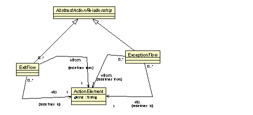
– ExceptionFlow Class Diagram
ExitFlow Class
ExitFlow class is a meta-model element that represents an implicit flow of control which should be taken when the corresponding block is exiting and has terminated normally or abruptly after executing the catch-block. For example, ExitFlow can be used to relate a try-block with the corresponding finally-block.
ExitFlow relationship represent an association between a TryUnit and the corresponding FinallyBlock according to the semantics of the programming language of the existing software system.
See example in section ExceptionBlocks
ExceptionFlow Class
The ExceptionFlow relationship represents an exception flow relationship between a TryUnit and the corresponding CatchUnit, or between a particular action element that can raise an exception to the corresponding CatchUnit.
| from:ActionElement[1] | the origin of the exception flow |
| to:ActionElement[1] | the CatchUnit to which control is transferred when an exception is raised |
The target action element of the ExceptionFlow relationship should be a CatchUnit
ExceptionFlow relationship represents a exception control flow between an action element that raises a certain exception, and the CatchUnit that handles this exception according the semantics of the programming language of the existing software system.
ExceptionRelations Class Diagram
The ExceptionRelations class diagram defines a set of meta-model elements that represent data flow relationships associated with exception handling mechanism common to various programming languages.
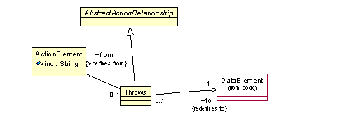
– ExceptionRelations Class Diagram
Throws Class
The Throws class is a meta-model element that represents throw-statements supported by several programming languages. These are the user-defined throws for exception, as opposed to the so-called normal system exceptions and runtime exceptions. Throw statements are essentially regular code elements, which simply have an additional relationship to their throw entity, using the Throws relationship.
See ExceptionBlocks and ExceptionFlow for representation of the control flow, related to exception handling mechanism.
| from:ActionElement[1] | The ActionElement that throws the exception |
| to:DataElement[1] | The exception data element being thrown |
Throws relationship represents an association between an action element that raises a certain exception and the data element that is associated with that exception. It is the implementer’s responsibility to identify and represent these association according to the semantics of the programming language of the existing software system.
InterfaceRelations Class Diagram
The InterfaceRelations class diagram defines KDM relationships that represent the usages of an “declarations” by the action elements. The classes and associations of the InterfaceRelations diagram are shown at See – InterfaceRelations Class Diagram..
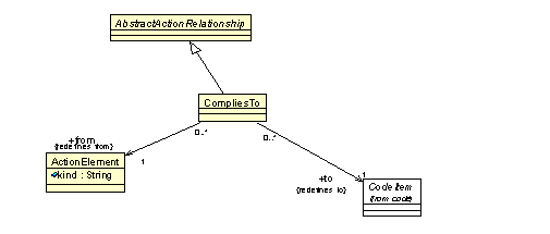
– InterfaceRelations Class Diagram
CompliesTo Class
The CompliesTo is a meta-model element that represents an association between an action element which “uses” some computational object, and the “declaration” of that computational object.
| from:ActionElement[1] | the origin of the relationship; action element that “uses” some computational object |
| to:CodeItem[1] | the “declaration” of that computational object |
The kind attribute of the CodeItem at the target of the CompliesTo relationship should be equal to “external” or “abstract”
- The action element which is the origin of the “CompliesTo” relationship should own a callable or data action relationship to some computational object and the target of CompliesTo relationship should be one of the declarations of that computational object
See InterfaceRelations section of the Code package chapter.
UsesRelations Class Diagram
The UsesRelations class diagram defines meta-model elements that represent associations between ActionElement and Datatype related to type cast operations. The class diagram shown in See – UsesRelations Class Diagram. captures these classes and their relations.
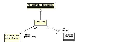
– UsesRelations Class Diagram
UsesType Class
The UsesType relationship represents a type cast or a type conversion performed by an ActionElement.
| from:ActionElement[1] | the action element that performs a type cast or a type conversion |
| to:Datatype[1] | the datatype involved in a type operation |
UsesType relationship represents an association between an action element which performs a type cast or a type conversion operation and the corresponding Datatype. The precise nature of the type operation can be further specified by the “kind” attribute of the action element. See the “micro KDM” chapter.
ExtendedActionElements Class Diagram
The ExtendedActionElements class diagram defines an additional “wildcard” generic element for the code model as determined by the KDM model pattern: a generic action relationship.
The classes and associations of the ExtendedActionElements diagram are shown in See – ExtendedActionElements Class Diagram..
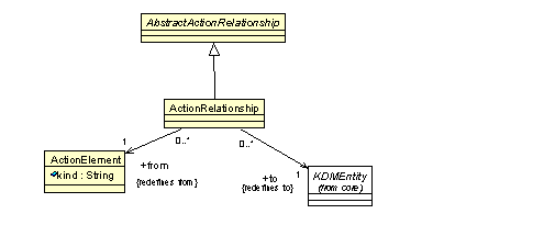
– ExtendedActionElements Class Diagram
ActionRelationship Class (generic)
The ActionRelationship is a generic meta-model element that can be used to define new “virtual” meta-model elements through the KDM light-weight extension mechanism
| from:ActionElement[1] | the origin action element |
| to:KDMEntity[1] | the target KDM entity |
ActionRelationship should have at least one stereotype
An action relationship with under specified semantics. It is a concrete class that can be used as the base element of a new “virtual” meta-model relationship types of the code model. This is one of the KDM extension points which can integrate additional language-specific, application-specific or implementer-specific pieces of knowledge into the standard KDM representation.
